Disclaimer: This website is for general information only and it contains general advice only, prepared in good faith based on our understanding of relevant laws. No one should rely on the detailed contents in this website without first obtaining advice from a suitably qualified person.
- Rainwater tanks
- Infiltration systems
- Permeable pavement systems
- Bioretention systems
- Grass buffers and swales
- Green roofs
- On-site detention (OSD) tanks
- Water efficiency
Rainwater tanks
The purpose of rainwater tanks is to capture and use rainwater to conserve potable mains supplies, and reduce stormwater runoff volumes and pollutants reaching downstream waterways. Rainwater tanks are suitable on all developments, however they are most effective on developments that incorporate large roof areas (to maximise capture), and have high water supply demand such as high-density residential dwellings or apartments, or developments with large gardens areas that require irrigation.
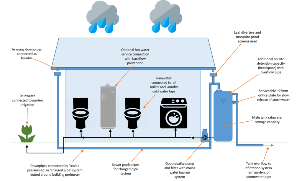
Figure 4 Simplified diagram of common rainwater tank installations
Design and application
To maximise rainwater re-use and reduce potable water supply, it is recommended that rainwater tanks be plumbed to all toilets, washing machines, laundry cold water outlets, and irrigation systems for any landscaped areas of the site. Rainwater tanks can also be connected to hot water services that include a water storage component, however these systems must comply with the National Construction Code (NCC) of Australia[1]. Considerations for connecting rainwater to hot water services are:
- ensure hot water is uniformly heated to 60° to “sterilise” it for contact use.
- install a fine mesh filter prior to hot water service inlet pipe to improve water quality – periodic maintenance is required
- ensure good quality pump is used to prevent fluctuation of water pressure and hence maintain a constant shower temperature
- install backflow prevention valve(s) as per NCC requirements.
Additional treatment is generally required when rainwater is to be used as a drinking water supply.
To ensure clean water supply in your rainwater re-use system, it is recommended that gutters are fitted with appropriate leaf guards, rainheads are fitted to downpipes, first flush diverters are fitted prior to the tank storage and mosquito screens fitted at the end of all pipes.
Rainwater tanks can include stormwater detention capabilities. These systems are referred to as combination retention/detention systems. The detention storage component is typically located at the top of the tank, with a restricted outlet orifice provided at a calculated height above the base of the tank to control peak flows. The detention component remains empty except during a rain event. The retention component is the permanent volume of stormwater stored at the bottom of the tank (below the restricted outlet orifice) that is available for use. Further information regarding detention systems is below.
Infiltration systems
Infiltration systems consist of a shallow excavated trench, soakage well or tank, designed to retain a certain volume of stormwater runoff. The stored water permeates into surrounding soils, significantly reducing runoff volumes, having provided a pathway for treated runoff to recharge local groundwater aquifers and, in turn, surface water resources.
There are several different types of infiltration systems that are available to the designer, each of which suit different sites and applications. These are:
- infiltration trenches
- infiltration basins
- soakage wells or pipes
- permeable pavement
- infiltration swales.
Infiltration systems function best when high-infiltration soil types are present (sand or mildly reactive clays). Many suburbs within the metropolitan Adelaide area are characterised by reactive clays not suited to these systems. An estimation of a sites soil type can be determined by referring to the Department of Environment and Water Nature Maps at https://data.environment.sa.gov.au/NatureMaps/Pages/default.aspx and the Soil Association Map of the Adelaide Region, Adelaide Geological Survey of South Australia 1972. Alternatively, for more accurate results, a geotechnical engineer can be engaged to undertake site soil classification and percolation testing.
Design and application
Guidance for the use of infiltration trenches and infiltration wells is outlined in WSUD: Basic procedures for “source control” of stormwater – a handbook for Australian practice[2].
The use of on-site gravel trenches or soakage well infiltration systems in proximity to buildings and other structures is restricted to soil types classified as class A (Stable, non-reactive), Class S (Slightly reactive clay), class M (Moderately reactive clay) or class M-D (Deep moderately reactive clay).
To protect nearby footings, slabs and other structures from cracking due to movement, the surface movement due to soils should be equal to or less than 25 mm, as defined in AS 2870 and where the following conditions exist:
- The slope of the natural ground does not exceed 1 in 10;
- The depth to rock is 1.2 m or greater; and
- The groundwater table is permanently below 1.5 m from the natural ground surface or the final ground surface, whichever is the lowest.
Pre-treatment of water for removal of debris and sediment is essential. Pre-treatment measures include leaf filters for roof runoff, and sediment sumps, vegetated swales, bioretention systems or sand filters for surface runoff.
The use of on-site infiltration devices is not usually recommended on sites classified as reactive soils of type H / H-D, H1 / H1-D, H2 / H2-D, E / E-D and P as defined in AS 2870, unless under advice from a structural engineer. For a description of these soil types see the Glossary.
| Soil type | AS 2870 Classification | Soil Hydraulic Conductivity (Kh)[3] | Minimum clearance from structures and boundaries |
| Sandy soils and sandy loam | Class A | 5 × 10⁻⁵ m/s (180 mm/hr) or greater | 1 metre |
| Sandy clay | Class S | between 1 × 10⁻⁵ and 5 × 10⁻⁵ m/s (36–180 mm/hr) | 2 metres |
| Weathered or fractured rock | Class A | between 1 × 10⁻⁶ and 1 × 10⁻⁵ m/s (3.6–36 mm/hr) | 2 metres |
| Medium clay | Usually Class M / M-D | between 1 × 10⁻⁶ and 1 × 10⁻⁵ m/s (3.6–36 mm/hr) | 4 metres |
| Heavy clay | Usually Class M / M-D | between 1 × 10⁻⁸ and 1 × 10⁻⁶ m/s (0.036–3.6 mm/hr) | 5 metres |
Infiltration pit sizing
A guide to sizing infiltration pits to capture the storm volume for a 1-in-5-year ARI 30 minute storm event in Adelaide is:
- 0.9 m diameter x 1.2 m high infiltration pit can connect up to 50 m2 of roof (~1 downpipe)
Details for sizing an infiltration pit can be found in:
- WSUD: Basic procedures for “source control” of stormwater – a handbook for Australian practice[4]
- Minister’s Specification SA 78AA – On-Site Retention of Stormwater[5]
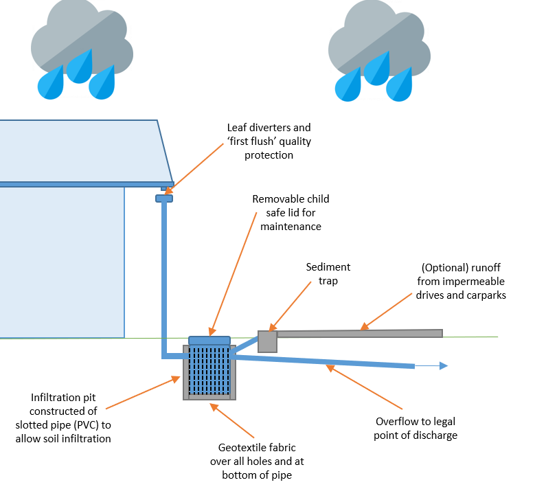
Figure 5 Example infiltration pit
Infiltration trench sizing
A guide to sizing infiltration pits to capture the storm volume for a 1-in-5-year ARI 30 minute storm event in Adelaide is:
- 0.9 m wide x 1.2 m high x 2.2m long infiltration pit trench connect up to 50 m2 of roof (~1 downpipe)
Details for sizing an infiltration pit can be found in:
- WSUD: Basic procedures for “source control” of stormwater – a handbook for Australian practice[6]
- Minister’s Specification SA 78AA – On-Site Retention of Stormwater[7]
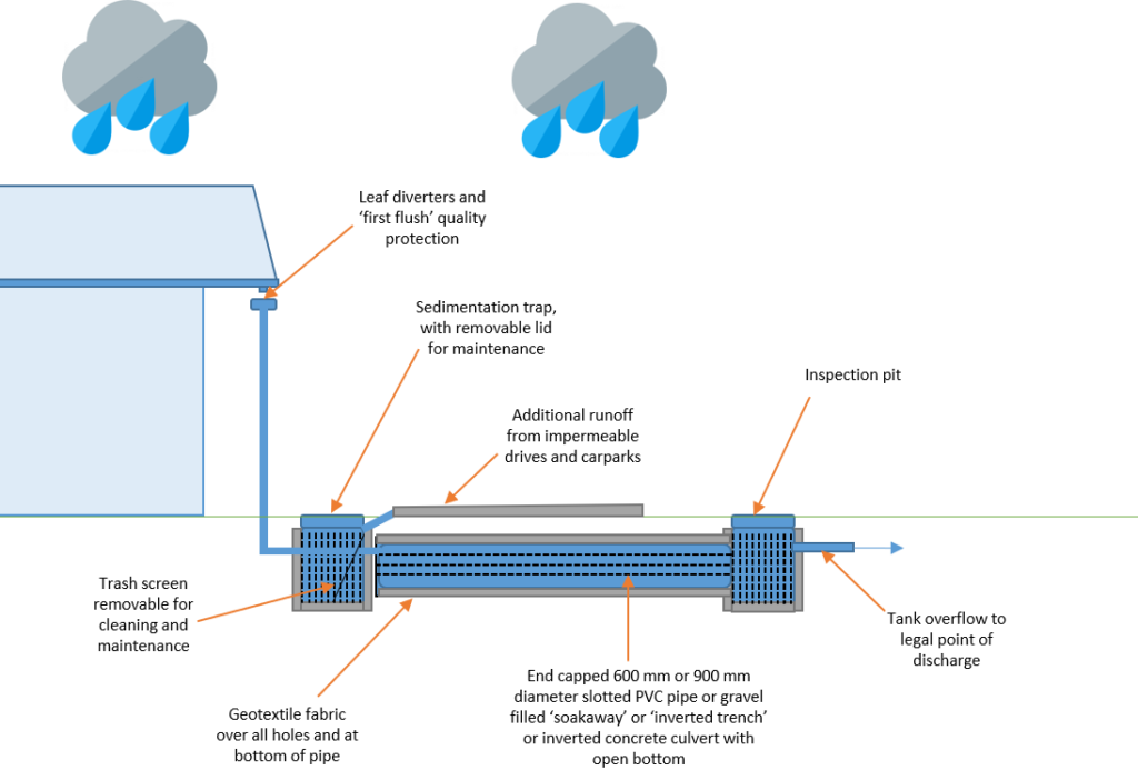
Figure 6 Example infiltration trench
Permeable pavement systems
Permeable pavement systems are pavement systems that allow stormwater to percolate through to a sub-surface course, from where it either infiltrates to the soil or is filtered back to the drainage system to subsurface soils or storages to reduce stormwater runoff. Underlying pavement layers can also include perforated pipes that allow the release of stormwater runoff into the receiving drainage system.
Permeable pavement systems provide two main advantages over regular impervious pavements: Improved water quality through filtering, interception and providing biological treatment; and reduced stormwater flow through infiltration and storage.
Permeable pavement systems commonly include interlocking block paving, porous concrete or plastic grids that provide structural stability to gravel or grassed paths, driveways and car parks. Single-sized gravel can also be used as an effective method of reducing stormwater runoff in low-traffic footpath and driveway areas.
Design and application
Pervious pavement systems fall into two distinct categories:
- Porous surfaces: Comprising a layer of highly porous material (e.g. specially designed concrete or asphalt).
- Permeable pavements: Comprising a layer of interlocking paving blocks (either made with porous material or specially shaped to allow the ingress of water by way of vertical slots) to allow runoff through to the underlying surface.
Interlocking pavements or other systems rated to handle traffic are recommended where high traffic loads can be expected
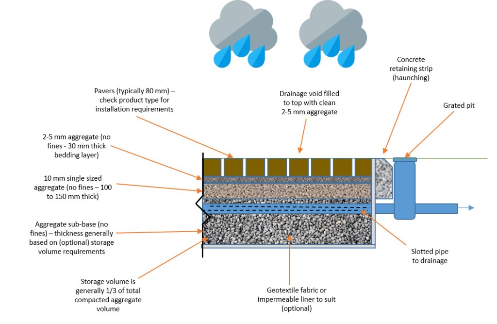
Figure 8 Example cross section of porous pavers
Bioretention systems (raingardens, bioswales and bioretention)
Bioretention systems are also known as raingardens, biofilters, bio-infiltration systems and bioremediation systems. Common types of bioretention systems are:
Raingardens improve stormwater water quality by slowly filtering water through the soil layer to the drainage pipe at the base. Stormwater flows are diverted and pollutants removed through the processes of settlement (sedimentation) binding with components in the filter media, and by the action of specially selected plants and the associated microbial community.
Bioretention basins are shallow planted depressions that assist in redistributing excess rain and stormwater runoff from the roof of a development, as well as pervious and impervious surfaces. The process assists the rainwater and stormwater runoff to infiltrate the underlying soil, recharge the groundwater and reduce peak flows from the development.
Bioretention swales and bioretention buffer strips serve an identical purpose as bioretention basins in that they reduce the volumetric flow of stormwater and improve stormwater quality. Bioretention swales usually include gravel storage volume. The void spaces in gravel helps store runoff from impervious areas (i.e. a carpark or driveway).
Design and application
For South Australian conditions, a rule of thumb guide is for the area of your raingarden to be between 0.5‑2.0% of the area of the contributing catchment (e.g. area of roof or other impervious surfaces draining to the raingarden). For more information and tools for sizing and designing a raingarden see www.watersensitivesa.insitewater.com.
For guidance on plantings in a raingarden or bioretention system see the Water Sensitive SA Guide to raingarden plant selection and placement[8]
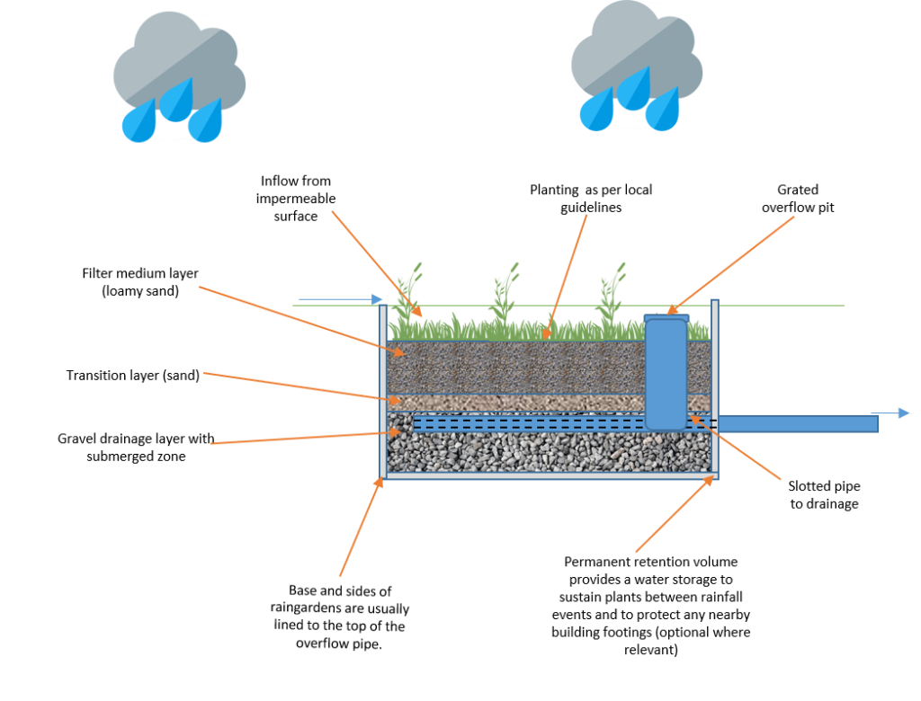
Figure 10 Bioretention raingarden.
Grass buffers and swales
Grass buffers are vegetated strips that convey hard runoff from an impermeable surface to a downstream drainage system. Buffers are effective in removing coarse and medium sized sediment from stormwater.
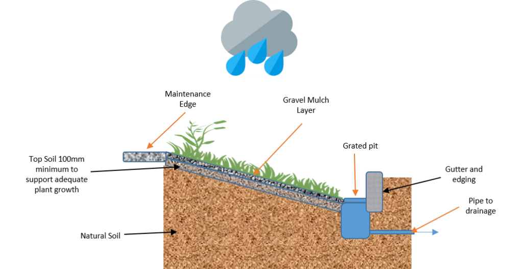
Figure 11 Grass Buffer simplified diagram
Grass swales are formed, vegetated channels that are used to convey runoff from impervious areas. They are typically shallow, linear, and wide. Grass swales can become features in the landscape, require minimal maintenance once established, and are hardy enough to withstand large flows. Grass swales differ from bioretention swales in that they normally have no underlying gravel and drainage layers.
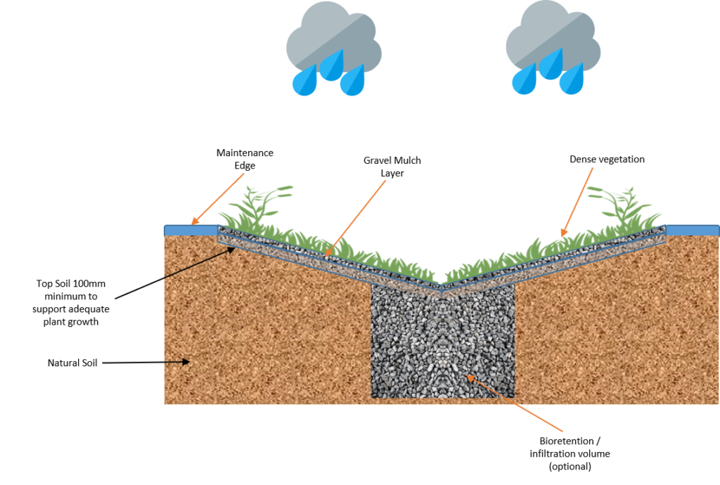
Figure 12 Swale simplified diagram
Design and application
Ensure levels are correct so that runoff can enter the buffer unimpeded. Buffer strips are typically grassy areas although a range of species could be used. More detailed technical advice on the design on these systems can be found in Water Sensitive Urban Design – Greater Adelaide Region Technical Manual, Chapter 11 (Swales and Buffer Strips) and the WSUD Engineering Procedures: Stormwater, which can be purchased at www.publish.csiro.au/book/4974
Green roofs and living walls
Green roofs and living walls can provide reduced energy costs, natural insulation, establish peaceful areas for individuals and a place for wildlife, as well as, absorb and treat stormwater. Additionally, green roofs improve air quality and aid in reducing the urban heat island effect; a condition in which cities and suburban developments absorb and trap heat.
Design and application
Green roofs and living walls consist of a series of substrate layers to support drainage on top of built structures, provide thermal insulation, and can ameliorate the urban heat island effect[9]. The layers incorporated within green roofs and living walls must accommodate drainage and protect the built structure from moisture and water ingress. This is achieved through the inclusion of a waterproof membrane in the design. High-quality root repellent systems are also required for green roofs and living walls to further protect the surrounding structures.
The most appropriate green roof for the Greater Adelaide region is a deeper substrate, which consists of depths between 150 and 600 millimetres of growing medium. Care should be taken that a structural engineer certifies that the building design can support a green roof, and that the design is resistant to heatwaves, as green roofs can “cook” in high temperatures, killing the vegetation. Design responses to improve performance in high temperatures can include deeper growing medium; water storage crystals; effective irrigation; partial shading with vegetation or structures, e.g. solar panels; and the use of annual native grasses and other summer heat resistant species.
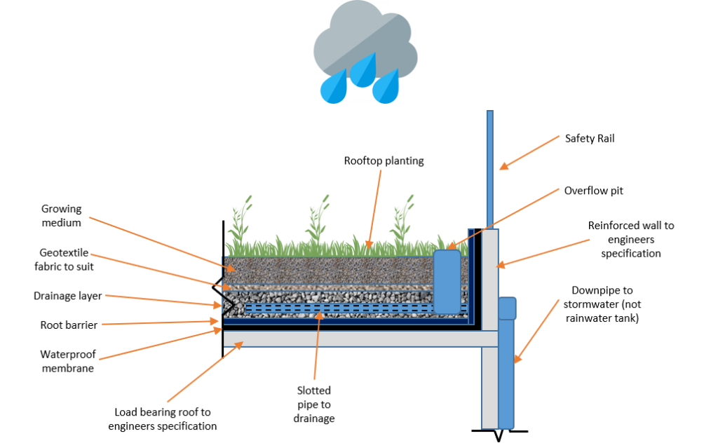
Figure 14 The various layers constituting a green roof design
On-site detention (OSD) tanks
Detention systems are similar to retention systems, however the captured stormwater runoff is only temporarily “detained” for a short period of time, with stormwater discharged at a controlled (reduced) outflow rate. This helps to limit impacts on the capacity of the receiving drainage system. Stormwater detention systems remain empty at all times, except during or immediately after a rain event occurs.
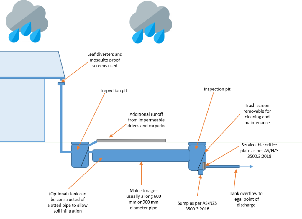
Figure 15 Typical underground stormwater detention tank
Design and application
Detention tanks are useful in areas where current stormwater infrastructure has aged – particularly where urban areas have densified over time, increasing impermeable areas connected to existing drainage systems. The installation of a detention tank aims to reduce local drainage overcapacity in existing infrastructure.
The effect is usually only locally beneficial, with overall catchment
flood volumes remaining the same. The flow rate from the tank may be regulated
by the size of the tank and orifice outlet. Onsite detention tanks must be
designed to suit the requirements of the proposed building development and its
location in the catchment. For more
information see local Council and stormwater authority guidelines and AS/NZS
3500.3 (Stormwater Drainage).
Water efficient fixtures and appliances
Developments must incorporate water efficient appliances and fixtures such as showerheads, dishwashers, washing machines, basins, kitchen taps and toilets. The Australian Water Efficiency Labelling and Standards (WELS) scheme is an Australian Federal system established to rate appliances based on their water efficiency. It works by assigning a relevant WELS rating (WELS Star rating) label to certain products.
Design and application
Projects should aim to meet best practice water efficiency standards wherever possible. The below recommended WELS ratings performance criteria has been specified in comparison with the industry benchmark.
Table 1 Water efficient appliances and fixtures – WELS Rating and associated water savings against industry benchmark, performance criteria and best practice
| Typical fixture | Minimum requirements (used in InSite tool) | Best practice |
| Basins | 4 Star WELS | 5 Star WELS |
| Kitchen taps | 4 Star WELS | 5 Star WELS |
| Toilets | 4 Star WELS | 5 Star WELS |
| Showerheads |
3 Star WELS (with flow between 7.5–9 litres/minute) |
3 Star WELS (with flow between 6–7.5 litres/minute) |
| Urinals | 4 Star WELS | 5 Star WELS |
| Dishwashers | 3 Star WELS | 5 Star WELS |
| Washing machines | 3 Star WELS | 5 Star WELS |
| Baths | Medium Sized Contemporary Bath | Small square tub/combined shower |
The 25% potable (mains) water reduction performance target compared to a building that has no water saving features can generally be met by using a combination of efficient water fittings and a rainwater tank to supply water for appropriate household uses. This section provides recommended fitting specifications in accordance with the Australian Water Efficiency Labelling and Standards (WELS) for water efficiency of fittings[10].
See Water Sensitive SA
Fact Sheet WSUD 02 for recommended rainwater tank sizes to meet both water
saving and stormwater objectives.
References
[1] See NCC Plumbing Code of Australia PCA (Volume Three), Australian Building Codes Board, latest version at https://www.abcb.gov.au/
[2] Argue JR (2004/2013) WSUD: Basic procedures for “source control” of stormwater – a handbook for Australian practice. Urban Water Resources Centre, University of South Australia.
[3] Water, Melbourne. WSUD Engineering Procedures: Stormwater: Stormwater (Kindle Locations 6606-6609). CSIRO PUBLISHING. Kindle Edition.
[4] Argue JR (2004/2013) WSUD: Basic procedures for “source control” of stormwater – a handbook for Australian practice. Urban Water Resources Centre, University of South Australia.
[5] Minister’s Specification SA 78AA September 2003 On-Site Retention of Stormwater is available online at https://www.sa.gov.au/__data/assets/pdf_file/0017/7046/SA_78AA_Onsite_retention_of_stormwater.pdf
[6] Argue JR (2004/2013) WSUD: Basic procedures for “source control” of stormwater – a handbook for Australian practice. Urban Water Resources Centre, University of South Australia.
[7] Minister’s Specification SA 78AA September 2003 On-Site Retention of Stormwater is available online at https://www.sa.gov.au/__data/assets/pdf_file/0017/7046/SA_78AA_Onsite_retention_of_stormwater.pdf
[8] See Water Sensitive SA Guide to raingarden plant selection and placement http://www.watersensitivesa.com/resources/publications-2/guidelines/bioretention/
[9] For more information see the Growing Green Guide: A guide to green roofs, walls and facades in Melbourne and Victoria http://www.growinggreenguide.org/
[10] See http://www.waterrating.gov.au/ for more information on WELS ratings